DART design tool
Introduction
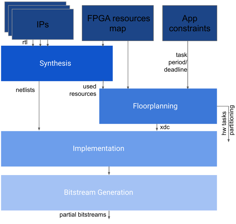
The FRED framework goal is to accelerate in FPGA a set of functions of a given application. In the proposed DART design flow, each function must match with a dart-compatible hardware IP. DART main input is a set of IP cores synthesized for partial bitstreams. The repository dart_ips presents a set of IPs ready to be used by DART. The second set of inputs is the Hw task partitions into reconfigurable regions or the Hw task timing constraints, depending on the mode DART is compiled.
DART design flow
The FPGA resource map input represents the FPGA internal organization that DART must know to perform its automated floorplanning optimization process. DART currently supports the following FPGA boards, where ZCU102 is the latest tested board:
Pynq board: with device XC7Z020-1CLG400C;
Zybo board: with the device XC7Z010-1CLG400C;
ZCU102 board: with Zynq UltraScale+ XCZU9EG-2FFVB1156 MPSoC;
Ultra96v2 board: with Zynq UltraScale+ XCZU3EG-SBVA484-1-i MPSoC;
DART is currently integrated with Xilinx Vivado 2020.2 for FPGA synthesis. The DART repository provides its source code, documentation, and additional examples.
Finally, DART generates a bitstream for the static part of the FPGA design and a set of partial bitstreams for each Hw task. In addition, DART also generates CSV configuration files describing the Hw task mapping into the FPGA floorplan. These configuration files are later read by FRED when the design is loaded in runtime.
The FLORA floorplanner
FLORA is the floorplanner used in DART to optimize the allocation of hardware accelerators on the FPGA fabric. The problem of floorplanning for dynamic partial reconfiguration consists in geometrically placing reconfigurable regions (RRs) within the available area of the FPGA. Producing a feasible floorplan means satisfying the resource requirements of the RRs while respecting the specific vendor-related technological constraints. In addition to feasibility, an optimal floorplan minimizes some performance metrics such as FPGA resource consumption or the maximum wire-length between RRs.
The resource requirement of RRs consists in ensuring that each RR must contain at least the maximum amount of resources required by all the reconfigurable modules that it hosts. Some of the vendor-related constraints on the Xilinx FPGAs include
RRs must be rectangular;
Vertical boundaries of RRs must not split back-to-back interconnect tiles;
Horizontal boundaries of RRs must be aligned with clock regions if the reconfigurable module is to be reset after reconfiguration;
RRs must not include some components of the FPGA (for 7 series devices this includes clock modifying logic, I/O related components, ICAP, XADC, etc;).
One of the major challenges in floorplanning automation is to adequately model the non-uniform distribution of heterogeneous resources on the fabric, since the model is tightly coupled with the definition of the aforementioned constraints.
FLORA solves the floorplanning automation problem and produces optimal floorplans for RRs by leveraging Mixed-Integer Linear Programming (MILP) optimization based on a fine-grained layout model of the computing resources (i.e., CLBs, BRAMs and DSPs) and system resources (i.e., interconnects, different functional blocks) on the FPGA.
FLORA floorplanner
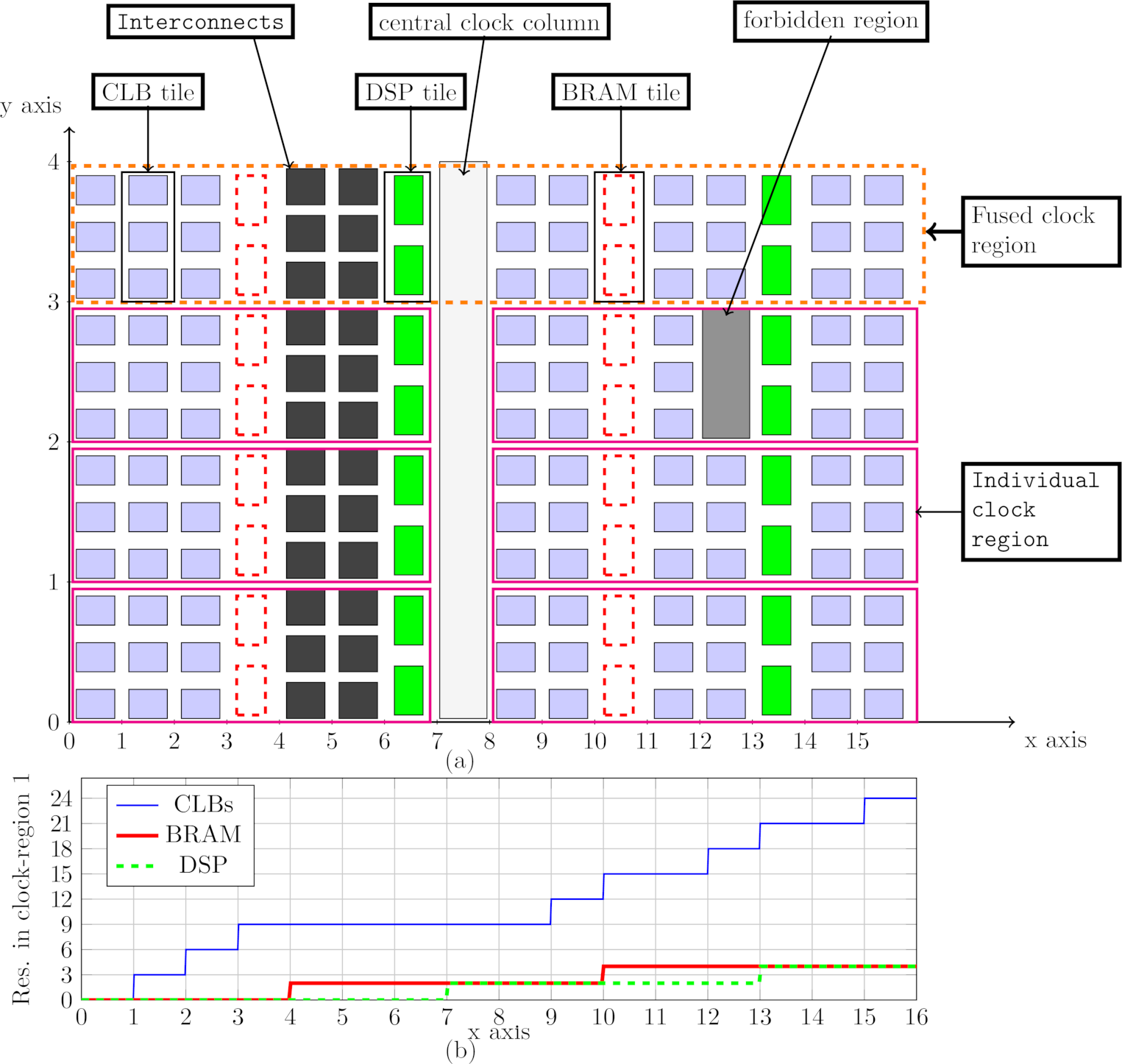
The resource distribution fingerprint is key to the fine-grained resource layout model in FLORA. The resource fingerprint is generated by overlaying a 2D discrete Cartesian coordinate system on the FPGA fabric whose origin is at the bottom-left corner. Each unit on the x-axis denotes a column of resources (CLB, BRAM, DSP, interconnects, central clock column), while each unit on the y-axis represents a single clock region that is fused with the horizontally adjacent clock regions. The resource fingerprint in FLORA, as illustrated in FLORA floorplanner, is the representation of the resources in the first clock region with a piece-wise constant function. It also contains the locations of all the forbidden components on the fabric.
The inputs to FLORA are the FPGA resource fingerprint, the resource requirements of the RRs, and the parameters the designer wants to optimize. Inside FLORA, the resource fingerprint and the resource requirements are translated into a set of MILP constraints and solved using a solver.
As illustrated in FLORA flow figure, the FLORA output is a constraint file (e.g., an .xdc file for Xilinx Vivado) that describes the layout of each RR according to the syntax specified by the design tool provided by the vendor. Before generating the final constraint file, FLORA provides an additional visualization tool that allows the designer to inspect the generated floorplan.

FLORA flow
Testing DART
DART is available for download. Further instructions can be found in DART repository and in the Getting Started section.
Reference
Biruk Seyoum, Alessandro Biondi, and Giorgio Buttazzo, FLORA: FLoorplan Optimizer for Reconfigurable Areas in FPGAs, ACM Transactions on Embedded Computing Systems. Presented at the International Conference on Hardware/Software Codesign and System Synthesis (CODES+ISSS 2019), New York, USA, October 13 - 18, 2019.